How to Comply with UAE Civil Defence Electrical Requirements in Industrial Buildings
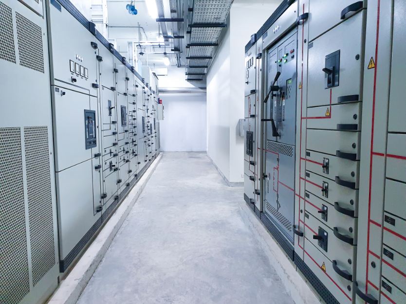
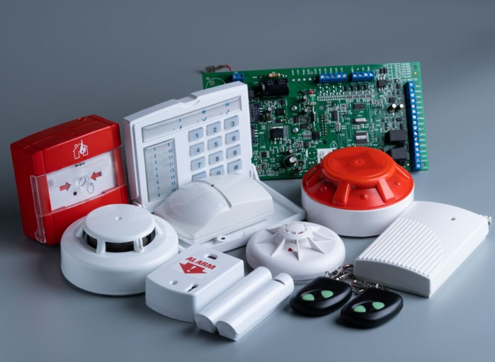
What’s New in UAE Civil Defence Electrical Standards: The Dubai Civil Defence (DCD) updated the UAE Fire and Life Safety Code in 2024 with enhanced electrical requirements for industrial buildings. Key updates include mandatory addressable fire alarm systems for facilities exceeding 2,000 square meters, increased emergency lighting duration requirements, and specific cable fire rating standards. These UAE Civil Defence electrical requirements in industrial buildings apply to all new construction and major renovation projects. The Abu Dhabi Civil Defence implemented aligned requirements through the Abu Dhabi Fire and Life Safety Code of Practice. Both codes reference international standards including NFPA and BS EN while incorporating UAE-specific provisions for climate and construction practices. The Ministry of Interior provides federal coordination ensuring consistent fire safety standards across all emirates. The Dubai Municipality coordinates building permit approval with Civil Defence requirements. The Emirates Authority for Standardization and Metrology (ESMA) certifies fire safety equipment including cables, detectors, and emergency lighting. Trakhees enforces Civil Defence requirements in JAFZA and other free zone industrial areas. The Dubai Electricity and Water Authority (DEWA) electrical regulations align with Civil Defence requirements for fire safety systems. The Regulation and Supervision Bureau (RSB) coordinates electrical and fire safety standards in Abu Dhabi. Understanding current UAE Civil Defence electrical requirements in industrial buildings ensures project approval and occupant safety. About Three Phase Tech Services Engineering Team: This technical guide is prepared by Three Phase Tech Services’ fire safety and electrical systems specialists. Our team has extensive experience in UAE industrial facility projects, Civil Defence approvals, and fire safety system design. Our engineers hold qualifications including Bachelor’s degrees in Electrical Engineering, professional certifications in fire protection engineering, and specialized training in UAE Fire and Life Safety Code requirements. Three Phase Tech Services maintains DEWA-approved contractor status and works directly with Dubai Civil Defence, Abu Dhabi Civil Defence, and Trakhees on industrial projects. Our team has completed fire safety electrical projects for manufacturing plants, warehouses, petrochemical facilities, and logistics centers. Learn more about our engineering team and certifications. Scope of This Technical Guide: This article provides practical guidance on UAE Civil Defence electrical requirements in industrial buildings under current codes and standards. Coverage includes fire alarm systems, emergency lighting, fire pump electrical supplies, smoke control systems, and cable fire ratings as of December 2025. Individual project requirements vary based on building size, occupancy classification, and hazard levels. For specific advice regarding your facility’s Civil Defence compliance requirements, system design, or approval documentation, consultation with qualified fire protection engineers is recommended. Contact Three Phase Tech Services for professional guidance addressing your specific needs. Understanding UAE Civil Defence Electrical Requirements in Industrial Buildings UAE Civil Defence electrical requirements in industrial buildings establish safety standards for electrical systems supporting fire detection, alarm, suppression, and evacuation. Industrial facilities present unique fire risks from manufacturing processes, stored materials, and high electrical loads. Civil Defence requirements address these risks through specific provisions for industrial occupancies ensuring adequate protection for personnel and property. The UAE Fire and Life Safety Code classifies industrial buildings based on occupancy type and hazard level. Light hazard industries with minimal combustible materials face different requirements than high hazard facilities storing flammable materials. Facility classification determines fire alarm system type, detector spacing, emergency lighting levels, and other electrical requirements. Compliance with UAE Civil Defence electrical requirements in industrial buildings involves multiple integrated systems. Fire detection and alarm systems provide early warning enabling evacuation. Emergency lighting ensures safe egress when normal power fails. Fire pump electrical supplies maintain suppression system operation. Smoke control systems prevent smoke spread protecting evacuation routes. Each system must meet specific design, installation, and testing requirements. The approval process requires design submission, review, inspection during construction, and final certification before occupancy. Dubai Civil Defence and Abu Dhabi Civil Defence conduct plan reviews and field inspections. Understanding requirements early in project development prevents costly redesign and construction delays. Fire Alarm System Requirements Fire alarm systems form the foundation of UAE Civil Defence electrical requirements in industrial buildings. System Type Selection Addressable Systems Dubai Civil Defence requires addressable fire alarm systems for industrial buildings exceeding 2,000 square meters. Addressable systems identify individual device locations enabling rapid response to alarm conditions. Each detector and manual call point has unique address displayed on the fire alarm control panel. Addressable technology provides faster fault identification and simplified maintenance. Conventional Systems Conventional fire alarm systems remain acceptable for smaller industrial facilities below 2,000 square meters. Conventional systems identify alarm zones rather than individual devices. Zone design must limit area to enable practical alarm investigation. Industrial facilities may require smaller zones than commercial buildings due to complex layouts. Detection Requirements Detector Types and Placement Select detector types appropriate for industrial environment conditions. Smoke detectors suit most industrial areas but may be unsuitable where dust, fumes, or steam cause false alarms. Heat detectors provide reliable detection in challenging environments. Linear heat detection suits cable trays, conveyors, and elongated hazard areas. Detector spacing follows UAE Fire and Life Safety Code requirements based on ceiling height and detector type. Industrial facilities with high ceilings may require reduced spacing or alternative detection approaches. Dubai Civil Defence reviews detector layouts during plan approval ensuring adequate coverage. Manual Call Points Install manual call points at exits and along evacuation routes per code requirements. Maximum travel distance to manual call points typically limited to 30 meters. Industrial facilities require additional call points at hazardous process areas. Weatherproof enclosures protect outdoor call points. Notification Appliances Audible notification appliances must achieve minimum sound levels throughout the facility. Industrial environments with high ambient noise require higher output sounders or supplementary visual notification. Visible notification appliances assist hearing-impaired occupants and supplement audible devices in noisy areas. Notification appliance placement ensures coverage throughout occupied areas. Actionable Takeaway Select fire alarm system type meeting Civil Defence requirements for your facility size. Design detection layout addressing industrial environment challenges including dust, heat, and high ceilings. Verify notification appliance coverage accounts for ambient noise levels. Submit complete fire alarm design for Civil Defence approval before